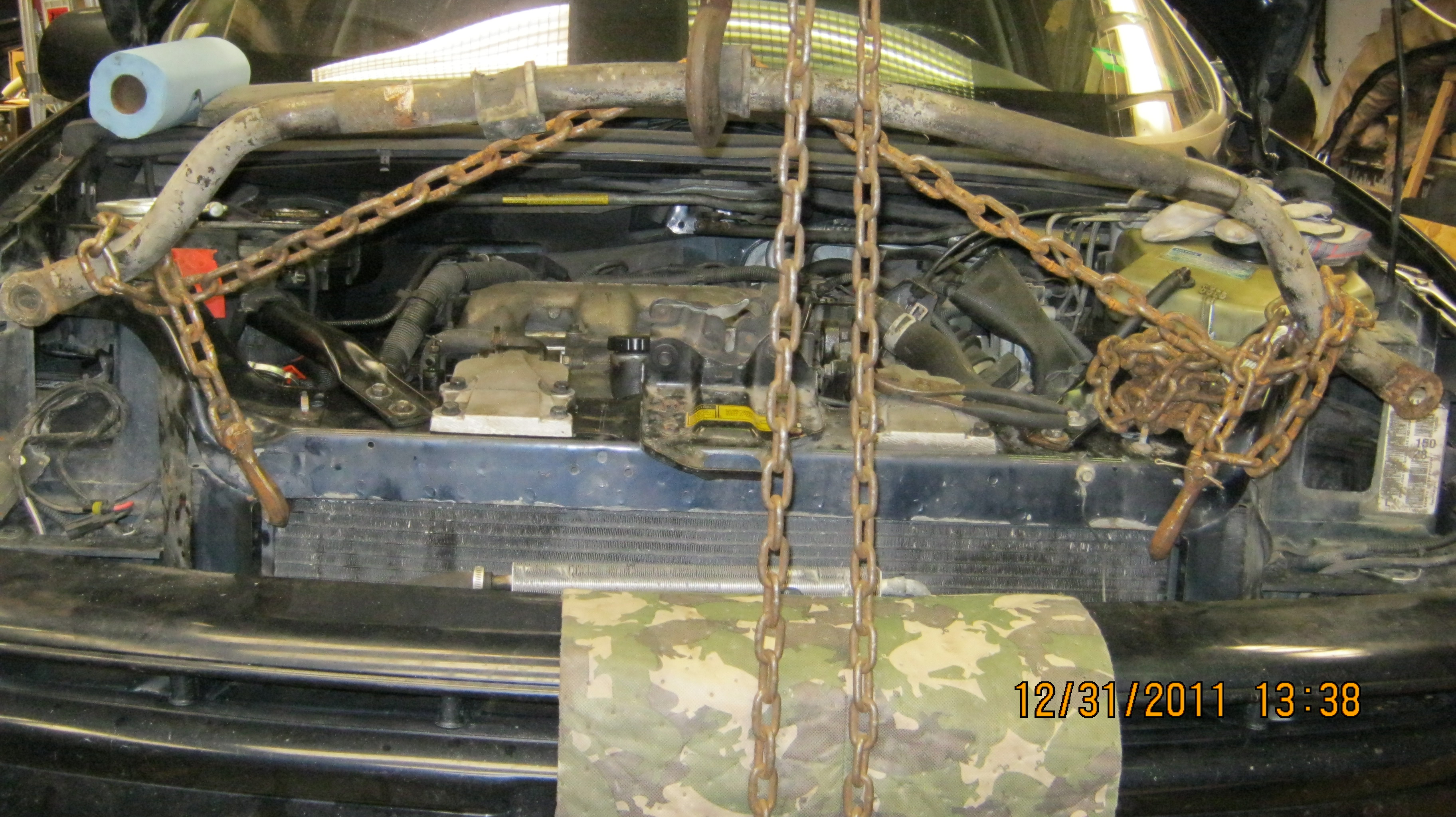
Olds Silhouette suspended via chain hoist
How to remove the engine and sub frame from Chevy Venture, Olds Silhouette, Pontiac Montana
1999 & Up
Having removed and installed this engine numerous times I thought I'd share my experiences with the reader in an effort to pave the way for anyone else considering this job themselves. I found nothing online that detailed how this is done and had to read and re-read my Helms shop manuals for the procedure. There is no substitute for experience or 'been there, done that' however, so let me try to illustrate my own experiences with this process. Your van should pretty very similar, but there are slight model differences, improvements, etc. so read and consider the whole task before taking action.
The engine and transmission are mounted on a sub-frame that can be unbolted and removed from below. GM expects you to raise the vehicle on a lift and then using their sub-frame removal tool, simply attach to and lower the frame away. Uh huh. . . Right. . .since we don't have one of those in the garage, how about this: We use either an overhead lift from a large tripod, heavy ceiling beam or large engine stand to lift the van body up, over the engine which we have left sitting on the floor as low as possible?
The lift needs to clear the engine and mounts and that means the bumper of the van needs to be about 4 feet high. This can be done with a good engine hoist—not those puny ones I've seen for sale at the local haveitall-mart. The top height of the hoist will need to reach about 6 feet to allow for 2 feet of drop on the chains that will support the body. I used an over head chain hoist
Olds
Silhouette suspended via chain hoist
for my last project, but in past I've also used cable hoists (I call them comeAlongs) sold at the local lumber yard:
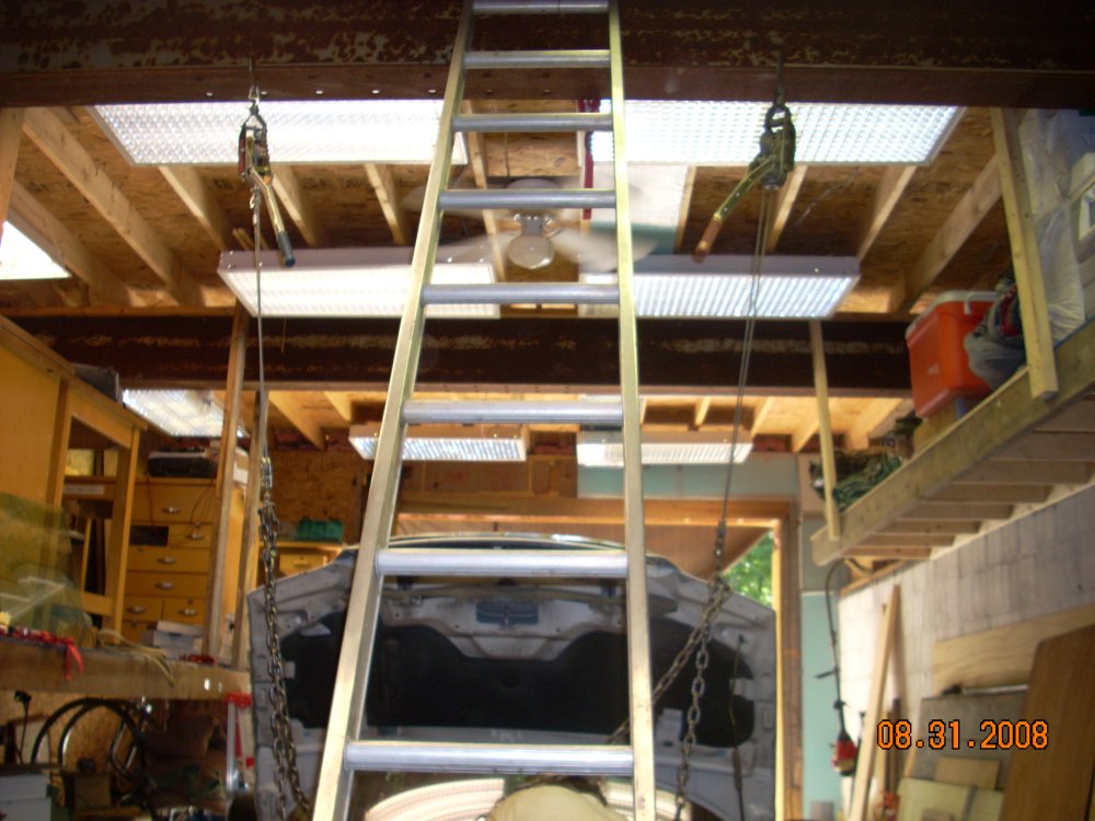
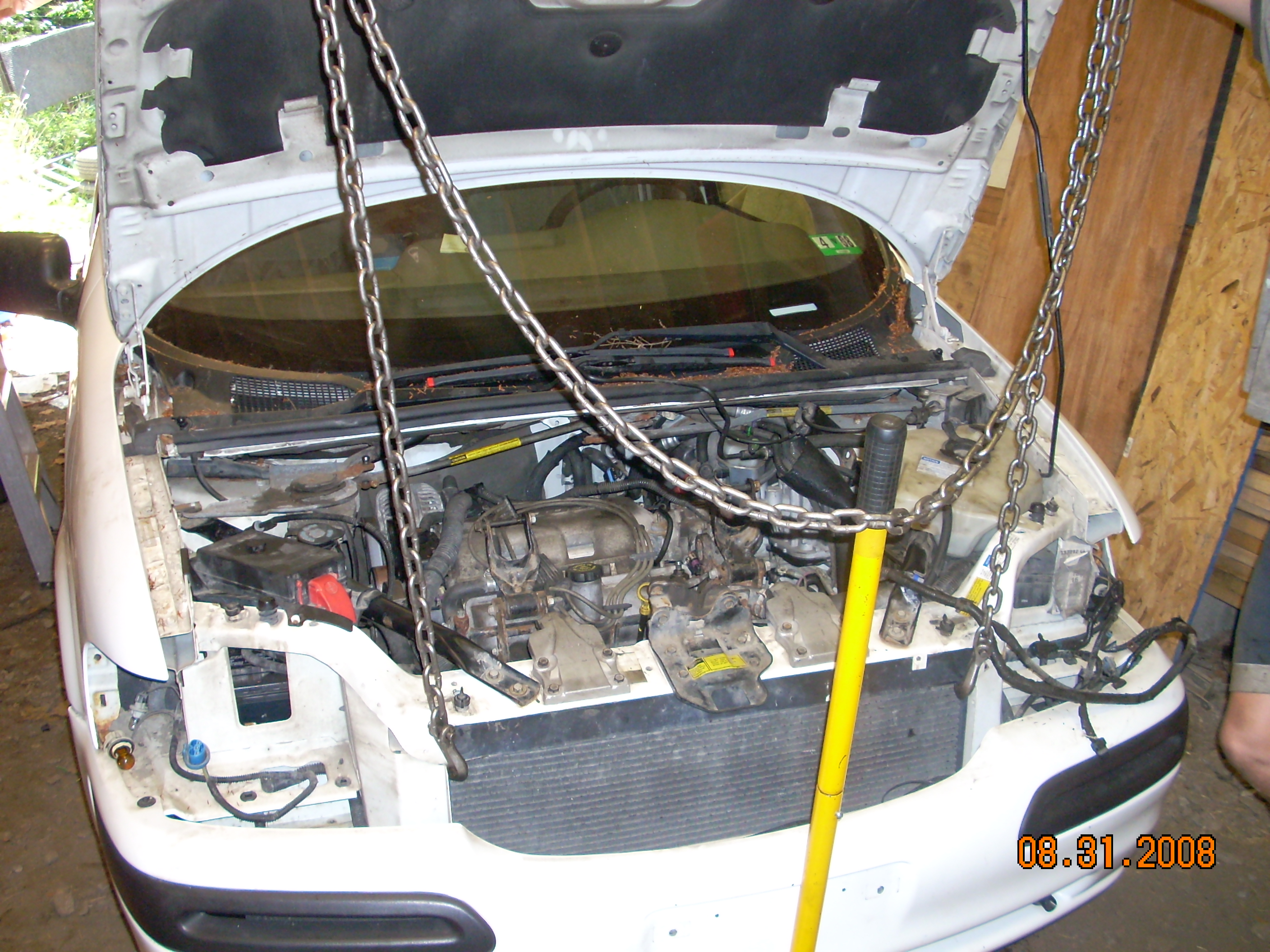
Chevy
Venture hanging via 'comeAlongs' from overhead beam
Note
that the chains are not lifting the weight of the engine and
transmission but only the body after the sub-frame has been released.
The lift points on the van are the body channels at either side of
the radiator. These are supported by the cross members which a bolted
from the front struts to the engine mount locations. Don't remove
these struts while the van is supportef from the chains. You will
need to purchase a steel hook that will fit between the body panel
and the radiator as shown.
When I used two comeAlongs, I spread them apart so the chains pulled outward slightly on the body. Using the single point lift from a chain hoist, I needed to make use of an old stabilizer bar (from this van in fact):
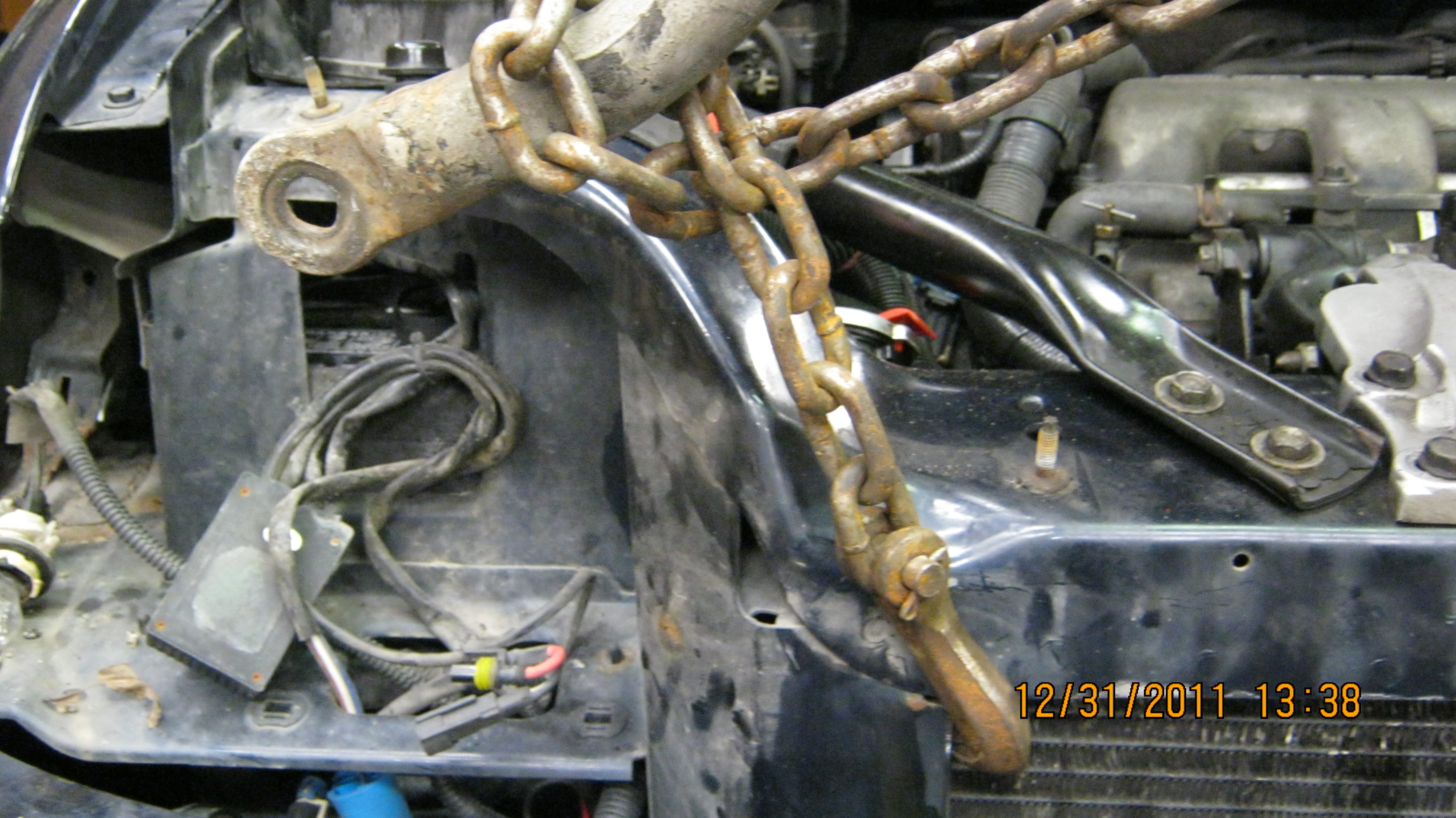
Detail
of chain & spreader bar used with single point lift.
The lift chain is wrapped around the sloped area of the bar so that as the van pulls down on the chain, the bar keeps the chain spread outward to the sides of the radiator. This portion of the body frame is reinforced from several directions, so unless rust is a problem, this lift point is more than substantial enough to support the required lift. You could rig whatever was on hand (4x4?) so long as it keeps the chains spread slightly outward to match the direction of body shape.
Getting started, here are the first steps to get the engine ready to remove:
The two front engine mounts need released. Just remove the two long bolts in the front of the mounts and rotate the arm up away from the frame mount. Unscrew the positive battery lead and lay it aside. I've forgotten that step a couple times now—its pretty important I've found. . .
Raise the van with a standard floor jack. I lift mine from the front by placing the lift at the center of the engine frame, just to the right of the oil filter area. This allows me to raise both wheels at once, and my jack will get the tires about 6 inches or so off the ground. Smaller jacks might require that you stop and place the stands under the frame in order to release the jack and use wood blocks to lift higher the 2nd time. However you approach it, the body needs to be raised high enough so you can get under the exhaust pipe to remove it, and you need room to work under there to remove fasteners, cables, etc.
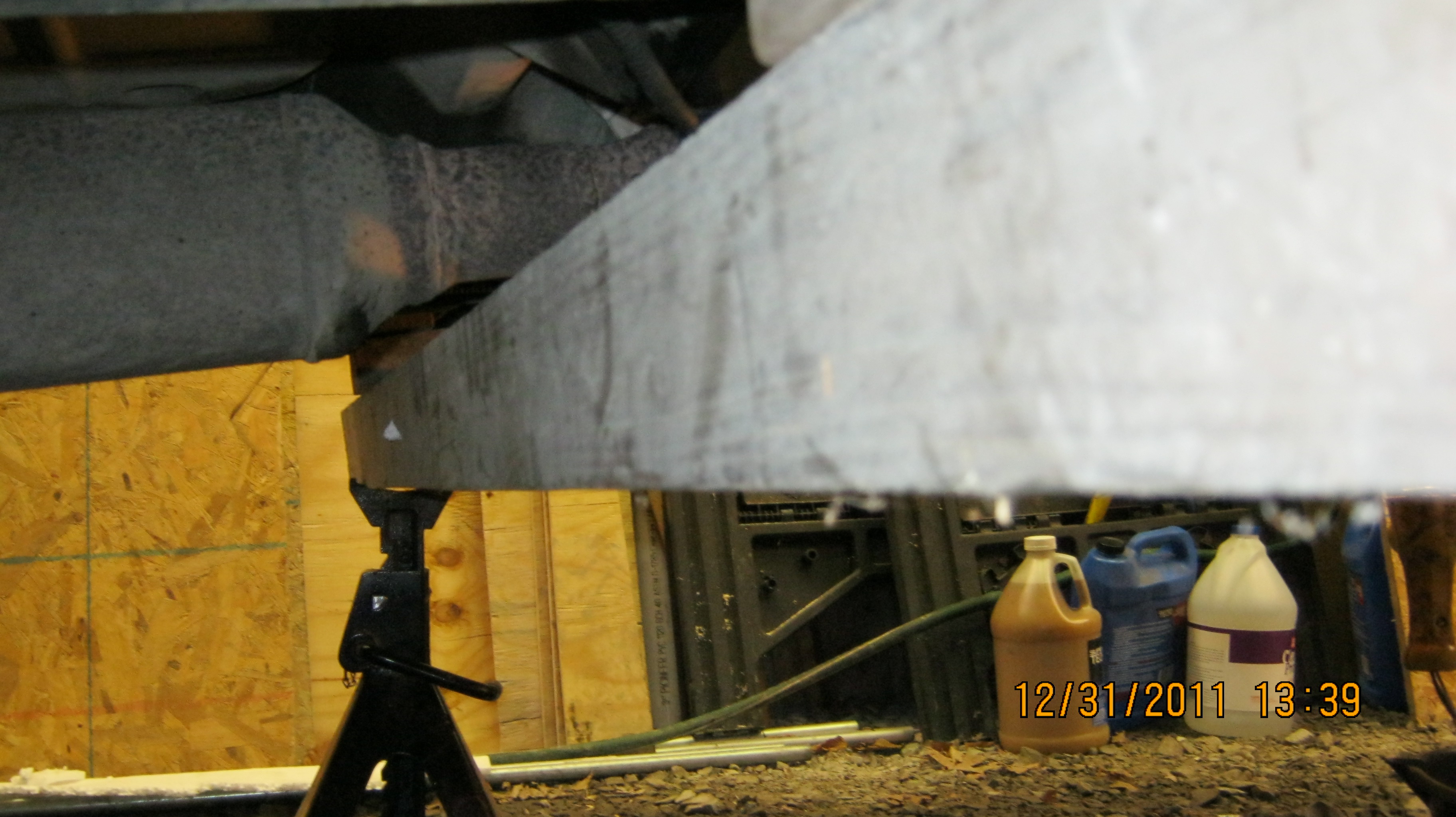
Jack
stands used to support the van prior to removing the subframe.
I support the van with two jack stands and a 4x4. I use the 4x4 because I want to also provide support for the exhaust pipe and I found that by setting the beam across the two jacks, the 4x4 provides a bit of extra sway stability. I don't like to crawl around under things that might fall on me!
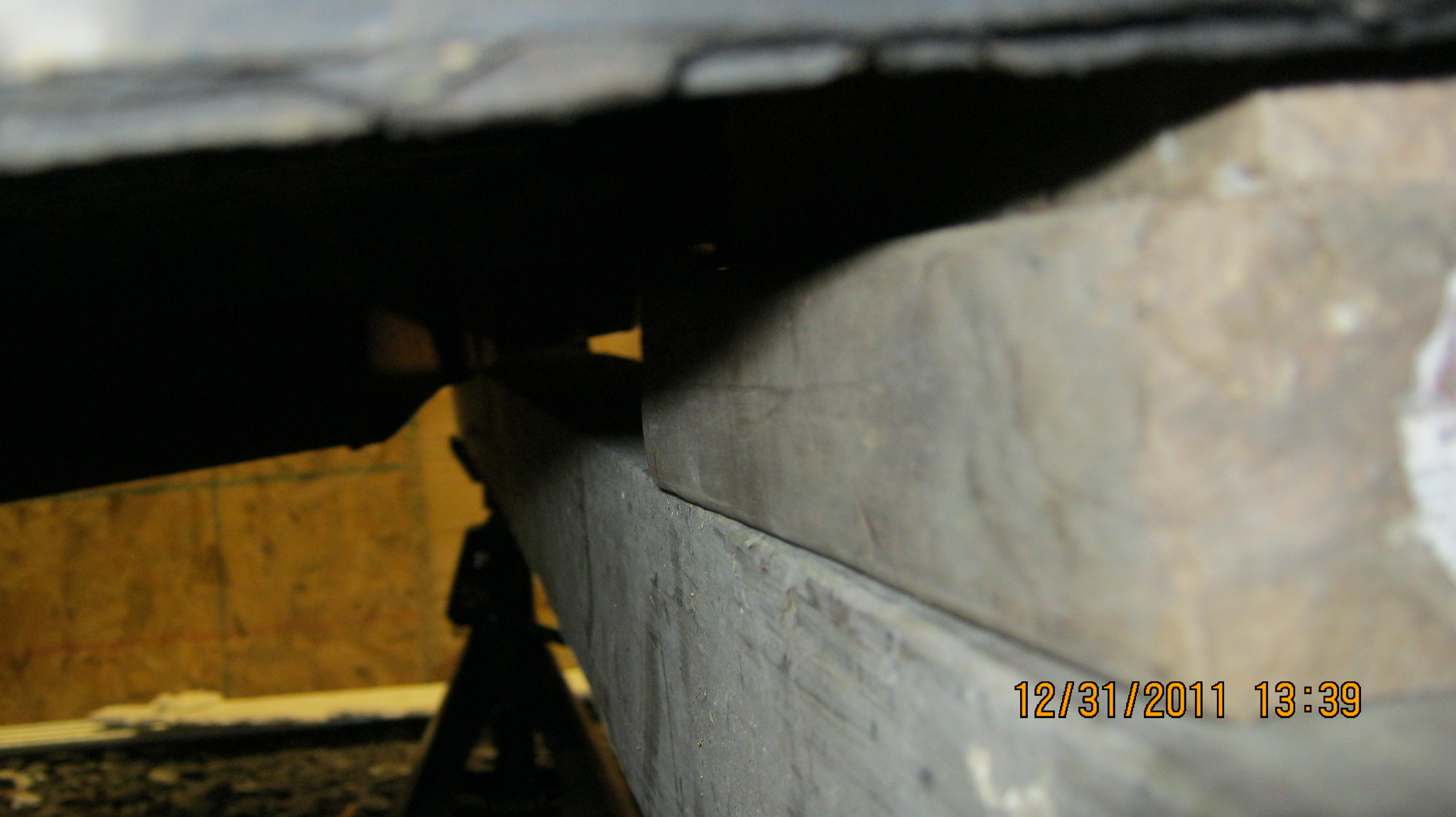
Wood
blocks used to support the frame and not crush the body edge of the
rocker panels.
There are several layers of wood blocks stacked up on the 4x4 so the lift point under the body avoids the delicate joint edges under the rocker panels and also protects the fuel and brake lines under the driver's side. The cross beam just back from the firewall will rest on the wood blocks and the beam. Once the vehicle is lifted and stable, its time to go to work.
Both wheels need removed and the caliper assemblies on the rotors must be disconnected. I use a short length of steel wire to hang the caliper on the upper strut spring, up out of harm's way.

Removing
the caliber bolts.

Hanging
the caliper assembly on the strut, up out of harm's way.
With that task done, I start underneath the vehicle at the downstream O2 sensor and the muffler hanger.
The
downstream O2 sensor and wire harness.
There is a cable harness that runs from the top of the radiator down, around the AC compressor, under the engine, around the transmission, and back to the rear O2 sensor. That's where I started, and the goal is to remove that harness from the chassis all the way to the cooling fans on the radiator.
The wiring loom is connected to the body by push in clips, Sometimes its easier to remove the clips, which I work out using needle nose pliers and a good shop light so I can see what I'm doing. Other times its better to open the retaining clip with a small screwdriver. The clips are easily damaged, so take your time and work each one out of its hole or open the clip. Each fastener is a challenge, but its important not to damage them or you will be paying for new ones.
The
downstream O2 connector and the exhaust hanger bracket which must be
removed.
The exhaust hanger bracket wraps around a frame cross member and 3 bolts must be removed. The exhaust will support itself until the two manifold bolts are removed from the exhaust entry flange. After the O2 sensor is unplugged and the cable harness disconnected, its time to find a very long socket extension and unscrew the exhaust flange from the engine manifold.
One
of the two nuts that need removed to lower the exhaust from the
engine.
I had little trouble backing the exhaust nuts away from the manifold. The exhaust pipe lowers down about an inch to rest on the 4x4 holding up the van. I always discard these exhaust nuts in favor of new ones when reinstalling. If ever there was a case for anti-seize lube, this is it.
Next, I continue with the wiring harness, locating the holding clips and removing or opening each in turn. The next connector is a sensor on the passenger side of the transmission housing just where the drive shaft exits:
A
speed sensor near the passenger side drive shaft needs unplugged.
Notice the exhaust flange at left.
Climb out from under the van and head back to the wheel wells. Remove the splash shields from both wheel wells at this time. You need the access to get at the wire harness on the passenger side.

The
driver side front splash guard and the clip that holds the ABS line
connector.
I like to use wire cutters to loosen the fasteners and lift the pins away from their seats. I switch to pliers once the pin is projecting enough to pull it free from the fastener. You need to preserve these clips unless you have purchased a box of replacements for re-installation.

Driver's
side ABS wheel sensor connector.
The ABS wheel sensors must be unplugged at the rear of the front splash shields. These connectors are clipped onto the splash shields from the engine side and you need to reach between the body and the engine compartment to find and release retaining clips on the connectors. Push the cable clip back towards the engine side on each front splash panel to free the splash shield from the cable and gain access to release the connectors. Remove all the clips on the plastic panels and set them aside.
This
is the speed sensor as viewed from the passenger side wheel well.
Now, continue from the passenger wheel well and release the cable harnes from the tie down clips.
The wire harness wraps around the drive shaft and is attached at a couple places, both hard to reach, but possible from the wheel well. Once disconnected, pull the wire harness around the drive shaft and hang it under the oil pan.
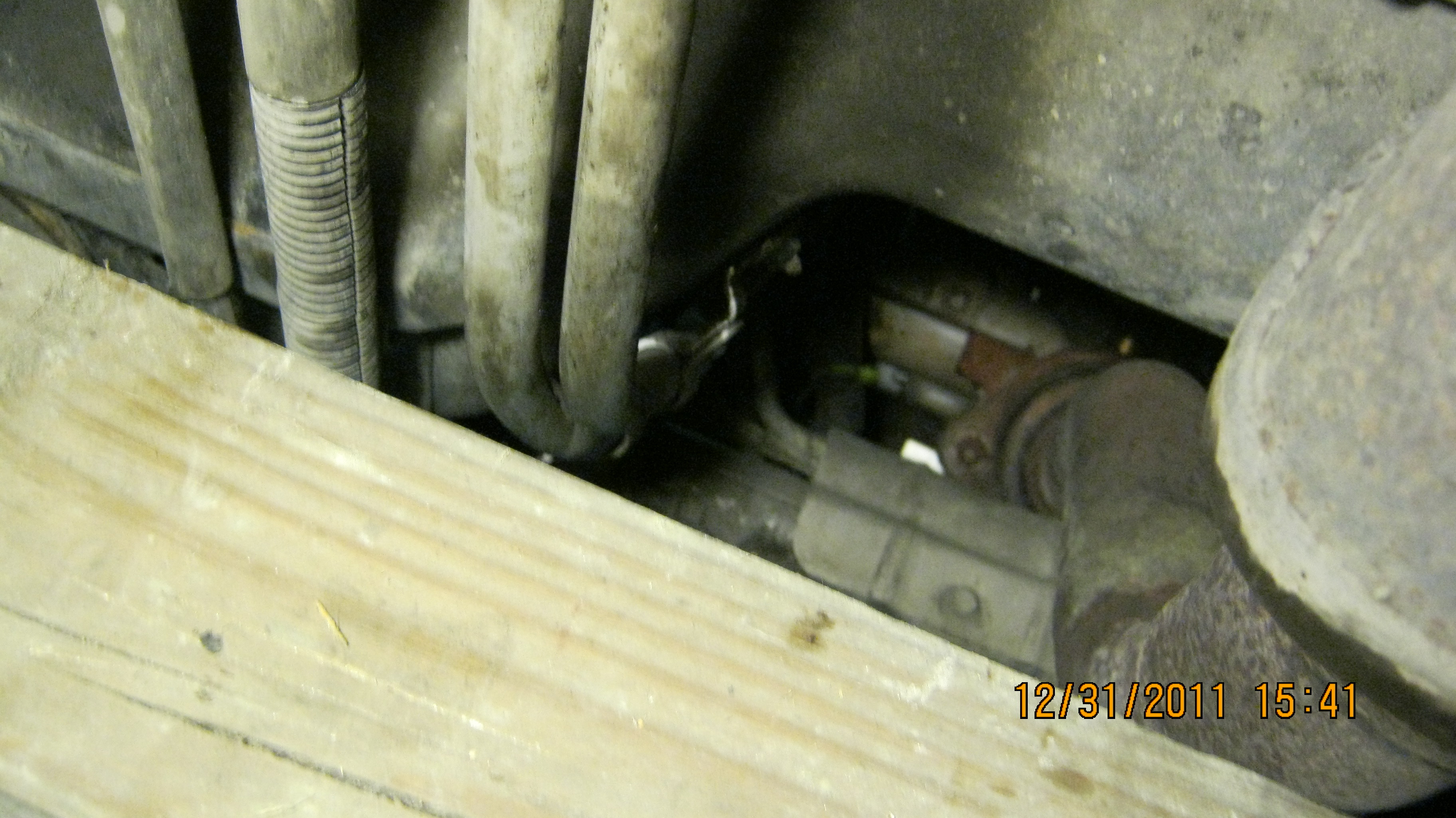
Next, its back under the engine to remove the wire harness at the oil level sensor, easy to see and reach.
Oil
level sensor
Once the oil level sensor is disconnected, follow the cable around to the front and under the AC compressor. I've seen several routes this cable can follow from this point, but connections to the AC compressor, the crank shaft position sensor, the oil pressure sensor (beside the oil filter), and a water temperature sensor (to the right of the oil dip stick) all need disconnected.

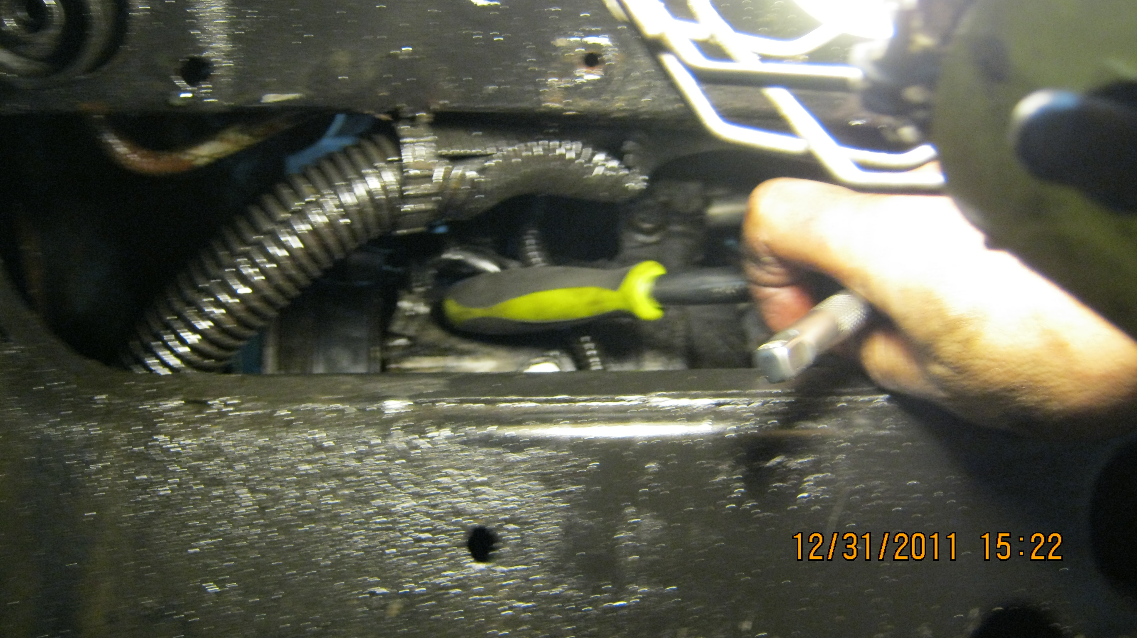
Lighted
area underneath the oil filter reveals the O2 wire harness we've been
removing and an engine
clip that holds the cable to the block.
Remove any clips, or bolted on clamps around this cable as well since it stays with the body while the engine goes down. It should come completely free of all engine connections with little trouble. If the space between engine and radiator is too cramped, you can leave it for now and re-visit again after the frame is lowered a few inches.
Working
from below, this is one of several clamps I had to remove to free
the wire harness from the engine.

Looking
down on the engine, this is the crankshaft position sensor located
just above the AC compressor.
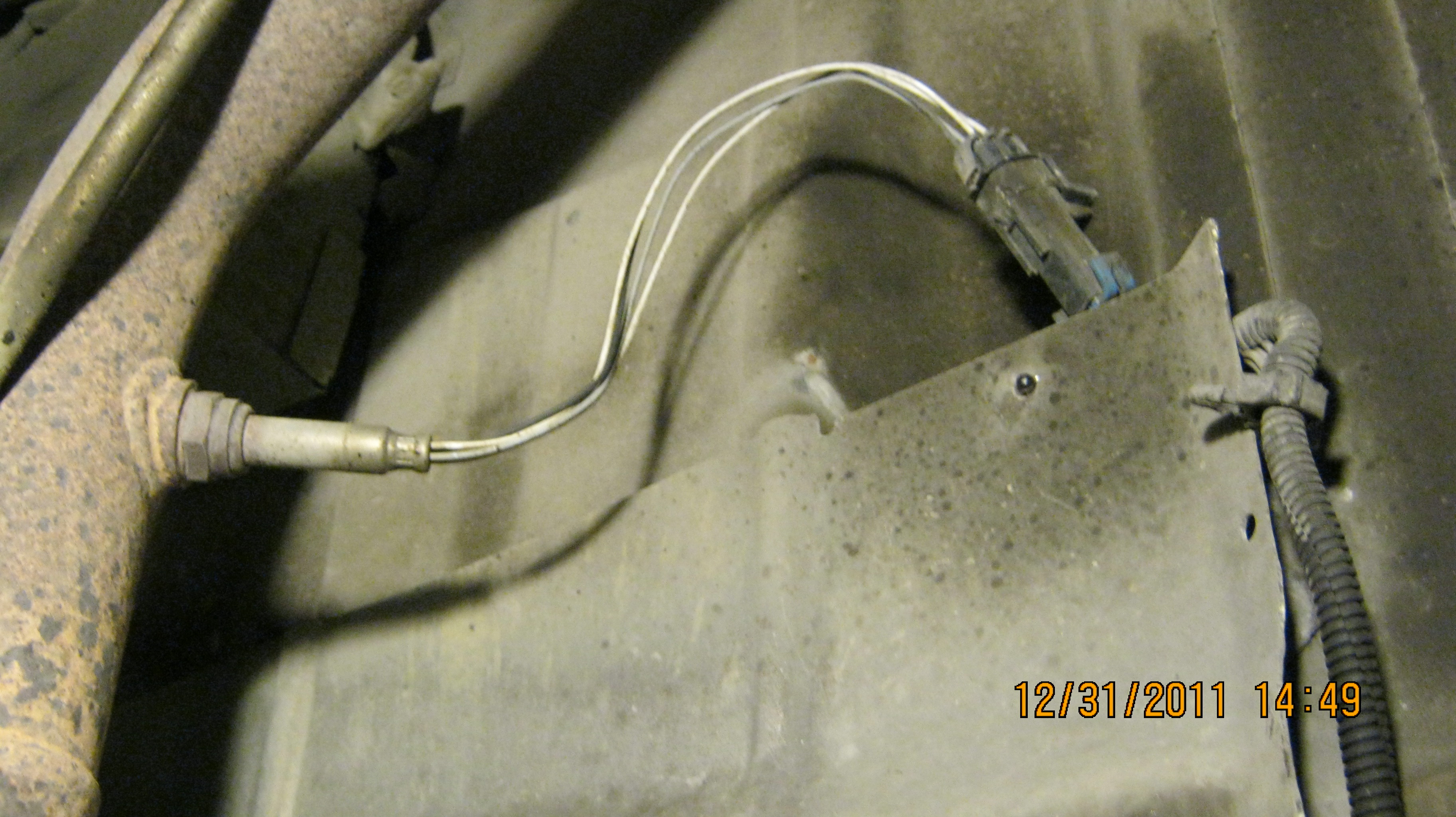
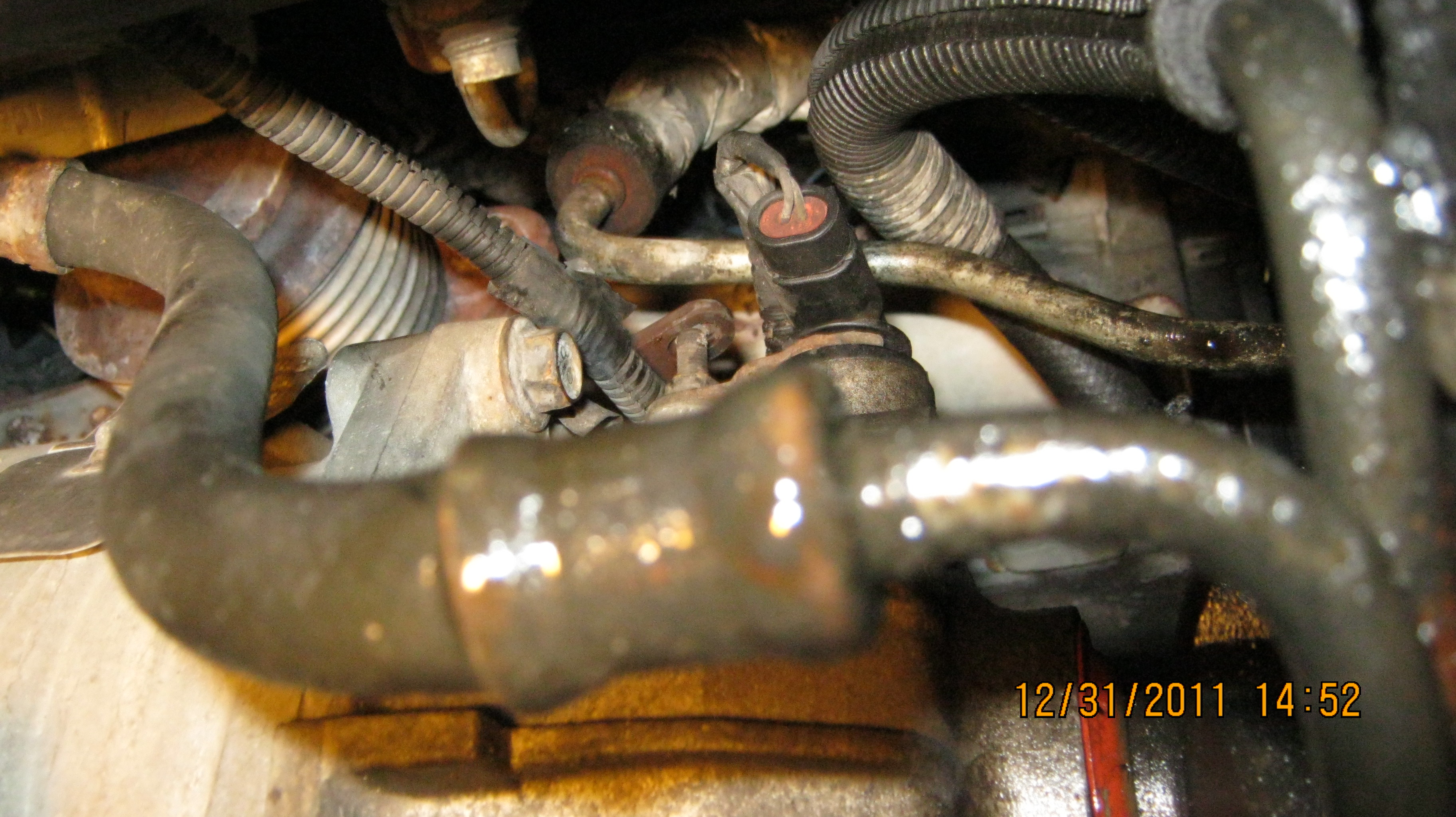
Don't' get up from the floor yet. Its time to remove the transmission lines from the bottom of the unit.

That's
a line wrench on the transmission cooler line. If you don't have
one, get one!
Don't forget to get the bucket ready to catch the transmission fluid that will leak out.

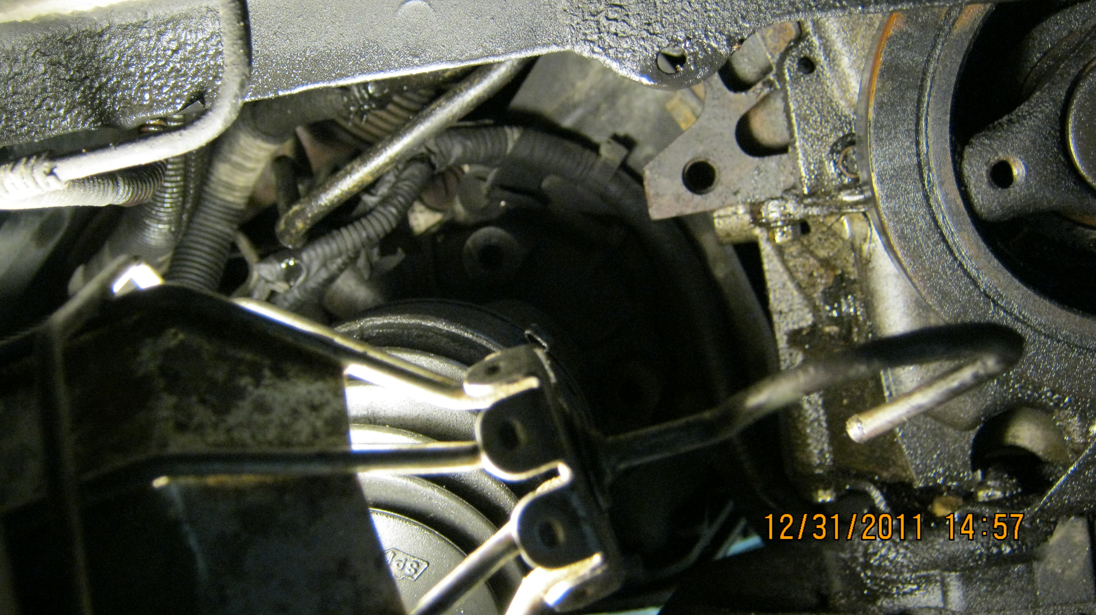
Both
cooler lines now removed and some fluid still dripping. Removing
ground clips and fasteners now.
While you are down there near the starter, get your wrenches out and remove the cables running to the starter and the ground lines attached at the transmission/engine housing.

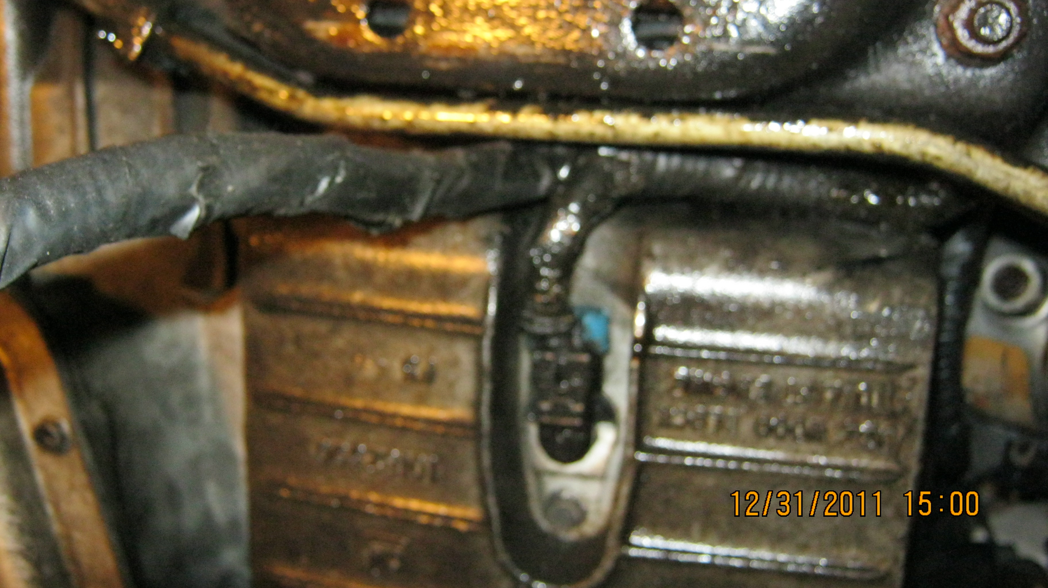
The
main ground clip near the bell-housing at the starter.
The bulk of the effort below the van is competed now, and its time to start the oil and the coolant to draining. The radiator drain is a plastic finger tab that should turn ¼ way loose and start the water flowing. Don't turn it more than that or the plug will come free and the coolant will stream way towards the back and make a mess. You can release the clamp at the engine port and disconnect the top radiator hose.
While everything drains, find your mini sledge hammer and start to work on the strut bolts over each wheel.

Driver's
side strut bolts, wet with penetrating oil prior to removal.
Remove the nuts on the strut bolts and beat on the ends of the studs to drive them out towards the front end of the van.
These bolts are built with a short neck beyond the thread, designed for you to beat on the end without damaging the threads.

The
strut bolts need driven out of their homes with a large hammer. The
wheel will not move when the bolts are removed since there is no
stress on the steering knuckle, and the slotted strut support will
hold the knuckle even without the bolts.
Don't let the bolts fly out and become lost when they come free. Before you stand up from the driver's side wheel well, reach inside near the firewall and start to work the intermediate steering shaft boot free from the power steering motor. This is a 2 inch plastic tube thats snapped onto the top of the rack and pinion motor. It must be freed as a first step towards sliding it up into the firewall and out of the way of the steering linkage.

The
brown ring in the center of the photo is the end of the boot that
must be unsnapped and slid upwards.
This effort will be much easier if the boot is clean, so you might want to use a shop cloth with soap and water to remove any oils and dirt that might be collected on the boot. This is one of the worst parts of this job, so approach it with determination and be forewarned that the boot will resist all efforts to dislodge it from its seat on the steering motor, and once free, it won't slide up into the firewall as advertised either!
I clean them carefully and apply lots of baby powder to help the sliding effort that will come later.
A view onto the air intake area. Everything must be removed to gain access to the steering shaft at the firewall.
Next its time to straighten out your legs and lower the van down to the floor. You won't need under the van again until the engine is removed, so put the 4x4 on the ground (careful with the exhaust pipe which will now be free to lay on the floor) and set the jack stands to the side.
You need to remove the pans of oil and coolant and position your flat dolly under the engine block. Judge your spot carefully; the balance needs to be good or the frame will tip over when free. Lower the van down with the floor jack carefully so the load doesn't crush the dolly and ruin your day. Lower the jack until the dolly is fixed in place under the engine and can't be dislodged—you will be placing your arms under this weight, so be certain its sitting well and things will not shift under the load.

My
flat dolly under the engine frame; the wire harnesses are hanging
down from the engine bay.
I removed the floor jack completely, but you might want to leave yours in place until the frame bolts are removed.
With the van on the ground, its easier to lean over the top of the engine bay and work.

The
view from above. Everything must be removed to allow access to the
intermediate steering shaft at the firewall.
Begin by removing the air intake filter and the MAF sensor attached to the intake shroud. Remove the rubber accordion tube and disconnect the breather host attached to it.

Removing
the throttle linkages.
The throttle linkage set can be removed and tucked under the windshield wiper to hold it back.
Fuel lines need be disconnected at this time. If you don't have inline release tools, you can fashion one by cutting a stiff plastic tube into quarter circles about an inch long. Cut off an inch of the tubing and split it longwise into 4 sections. These can be placed around the steel fuel line and slid into the connector to release the clips inside. If these connectors are new to you, make sure you purchase a tool before starting this job. Once you have used the tool a couple times, its easy to understand what is needed to free the clips and release the connectors. I've lent my tool out and simply make a new one from tubing when I need to now.

Fuel
lines released from their connections and the heater hose feedline
shown released from the engine connection. That's the EGR valve at
upper left and the tranny dip stick tube at center.
You can remove the transmission linkage now and the shift indicator switch as well. These are on top of the tranny down towards the firewall and are the last things preventing you from reaching the steering shaft and its protective boot.

The
shift linkage on the transmission with the shift indicator switch
underneath at the rear. Two bolts on each plus a nut at the end of
the linkage will remove all hardware. The shift cable can be tucked
up under the wiper arm with the throttle cables.
You can remove all the hardware associated with the shifter linkage and indicator switch and lay it aside. Don't mix the bolts up with others since tunique lengths are used to attach this on the transmission housing. On top of the transmission, the wiring harness must be unpluged from the transmission. If you don't know how, this can be really challenging to remove. Grasp the connection at the 9 O'clock and 3 O'clock position and squeeze while pulling out. It should come right off. If not, use some lubricant spray and try again. It really does come right off, believe it or not.

This
connection on top of the transmission can be tricky to remove, but
when squeezed just right it will come off freely.
The intermediate steering shaft boot needs to be slid up and into the firewall to gain access to the shaft coupling.

I
took this photo and still have trouble seeing the steering shaft boot
at the center of the picture.
Now its time to wrestle with that boot covering the steering shaft. I really have a hard time with this step, mostly because get lazy and don't clean the grease from my hands or don't clean the boot before I start. Be warned, this can be frustrating. With plenty of babypowder and clean hands, I manange to twist and push and pry the boot up and into the firewall out of the way. The steering linkage is exposed and the bolt ready to remove.

Steering
shaft linkage almost exposed.

Intermediate
steering shaft exposed and linkage separated. Upper shaft pushes
back into firewall. Note the baby powder everywhere.
That was really the worst part of this job! With the shaft linkage removed and the upper shaft pushed back into the firewall, only a few wiring connections are left to unplug. Most of these are to the rear of the engine. No need to scrape up your knuckles however. Since the engine is coming out, lets just lower it down a few inches before removing the wiring from the top of the engine.
On the left side, just above the power steering pump, remove the vacuum line from its connection at the back of the manifold behind the alternator. Store that line over the battery area where it won't be caught by anything.

The
vacuum line over the power steering pump must be removed.
With that done, grab your large breaker bar and head down below to remove the four frame bolts. Remove the front two first since if anything is not set right you won't risk your arm should the dolly collapse or anything untold happen. The bolts are about 6 inchs long in front, 5 inches in back. If everything is solid with the front bolts removed, you can reach under the body and remove the back bolts too. The bolts are tighten to 120 foot pounds which can be hard to release on the way back out. You should be using a half inch socket set and at least an 18 inch breaker bar here.
With all 4 bolts in hand, its time to start lifting the van over the engine frame. There are lots of things yet to be disconnected, so only lift it a few inches at a time while things are removed and disconnected. First you will need to pull the front bumper forward and over the engine cradle frame or it will break as the body goes up over the frame.

This
is the passenger side frame bolt site viewed through the bumper
slots.
You need to reach in and pull and separate the bumper supports over the frame end as the body is lifted. I had to replace my lower bumper support bracket because I missed this step the first time. You may want to take the extra time an just remove the whole front bumper before starting the lift. This takes only half an hour or so and makes things much easier to clear the body from the frame.

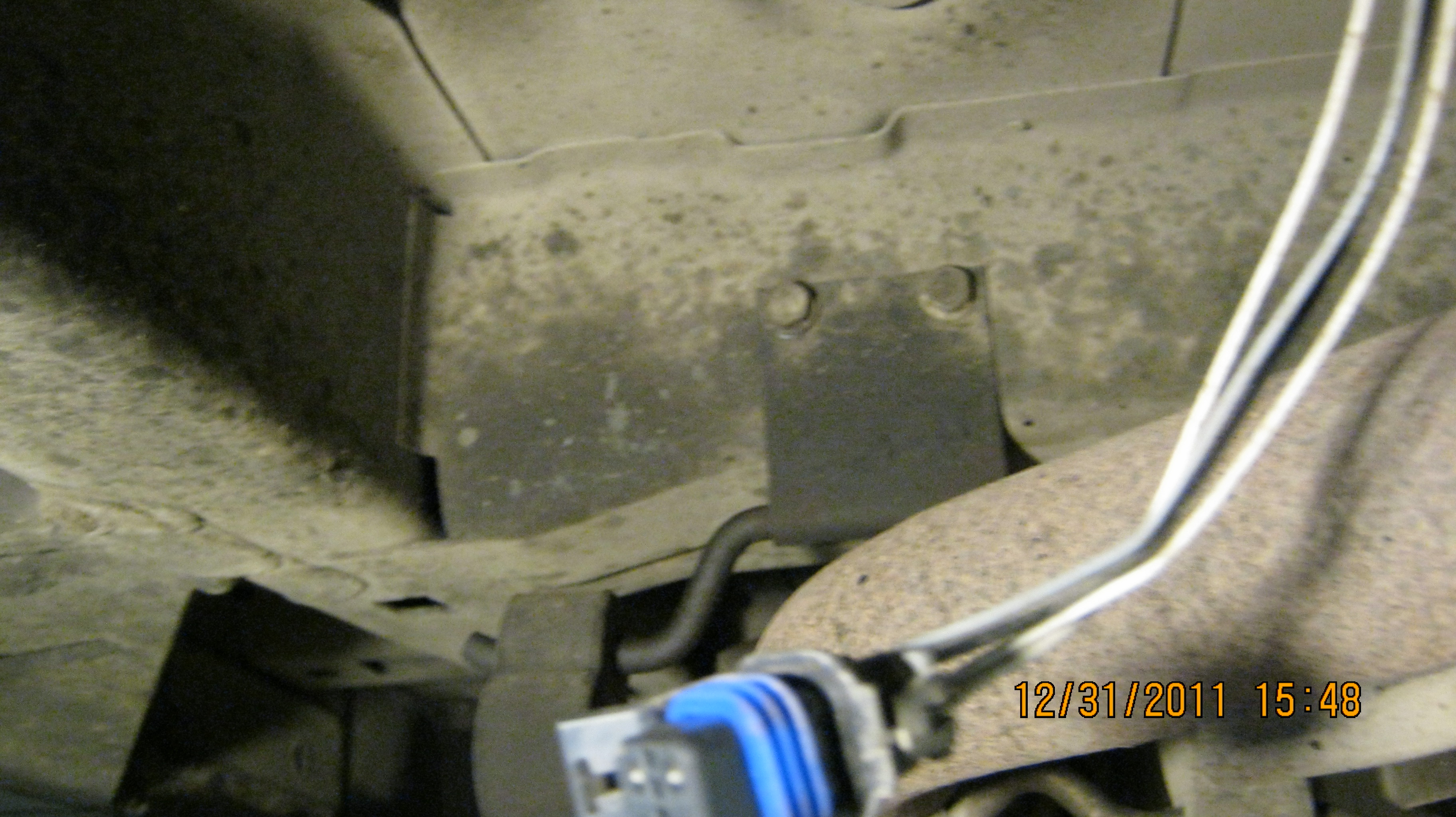
With the frame separation no more than 5 inches, you need to reach up and remove the coolant hose from the bottom of the radiator near the AC compressor. There should now be room to remove the lower most bolts holding the compressor to the engine block. There are 3 bolts used, two in front near the pulley and one in back. The two lower bolts are long while the upper one is shorter and can be removed last. Use a wire to hang the compressor to the frame since it stays with the radiator. If you had trouble freeing the long O2 wire harness, it should now be easy to see and remove and clips and connections near the oil filter.

Camshaft
position sensor plug below power steering pump.
Back to the top of the engine, you should have plenty of room now to reach back and unplug all the connections and harness clips that run from the throttle body area, back behind the coil packs and behind the alternator where the injectors connect to the wire harness. You need to unplug the vacuum booster hose and the rear heater hose connection. Don't forget to unplug the cam shaft position sensor in front of the power steering pump and unclip or open any fasteners on the left engine mount.

Wiring
harness must be released from the starter and transmission housing on
the right.
With the coolant hose removed from the radiator, and the sensor harnses unplugged on top of the engine, you can now lift the van another 5 inches to provide more access under the bumper to release the wiring harness around the starter and the transmission cooler lines which may be secured to the transmission housing.